Opening a set of house plans for the first time can feel like trying to read a language you have never learned. You may recognize the kitchen and bedrooms, yet wonder what the circles, dashed lines, numbers, and arrows are telling you. Even a familiar room can look surprisingly different when it is reduced to lines on a page.
You do not need to become a builder or learn to calculate structural loads to take part in reviewing your home. You need a clear way to navigate the drawings, understand what each sheet explains, and recognize when to ask a question.
This guide explains how to read house plans as a homeowner, from the cover sheet to the construction details. The central idea is simple: a construction drawing set is a communication system. Each drawing explains part of the home, and the drawings must be read together.
What house plans are—and what they help you decide
Construction drawings describe the home’s layout, appearance, dimensions, materials, and important assembly requirements. They help the project team communicate what is intended, coordinate its work, and identify questions before those questions become changes on the jobsite.
A floor plan downloaded from a listing or a sketch prepared during early design is not necessarily a complete construction drawing set. Preliminary drawings help you explore ideas. Permit and construction drawings develop those ideas with the information needed for their intended use. The sheets and supporting documents required vary with the project and location.
A complete project may also involve specifications, engineering documents, surveys, product selections, and drawings prepared by suppliers or trades. Ask your designer what is included, what is still being developed, and which additional documents belong with your set. A beautiful rendering can help you picture a home, but it cannot answer every construction question.
Start with the cover sheet, not the kitchen
Before studying individual rooms, confirm that you are looking at the correct project and the current drawing set. The cover sheet and title blocks—the information panels along the edge of the sheets—usually identify the project, sheet title, sheet number, date, and issue or revision information.
Look for a drawing index. This is the table of contents for the set. It helps you find floor plans, exterior elevations, sections, foundation drawings, and other information without searching every page. Sheet-numbering systems vary, so use the index instead of assuming a particular letter or number always means the same thing.
Read the general notes and the legend explaining abbreviations and symbols. Some notes apply across the project; others apply only where they are referenced. If a note seems unrelated to your home or conflicts with another drawing, flag it for clarification. Do not decide for yourself that one instruction can be ignored.
Understand what each type of drawing shows
Site or plot plan: the house on the property
When included, this drawing places the building in relation to the property. Depending on its scope, it may show boundaries, the driveway, setbacks, utilities, existing features, and proposed improvements. Grading and drainage information may be on separate drawings. A site drawing helps you connect the front door and garage to how you actually arrive at the home.
Check orientation as well. The top of a floor-plan sheet is not automatically north. Use the north arrow where provided, and ask how the house’s position affects daylight, views, privacy, and outdoor access.
Floor plans: how spaces connect
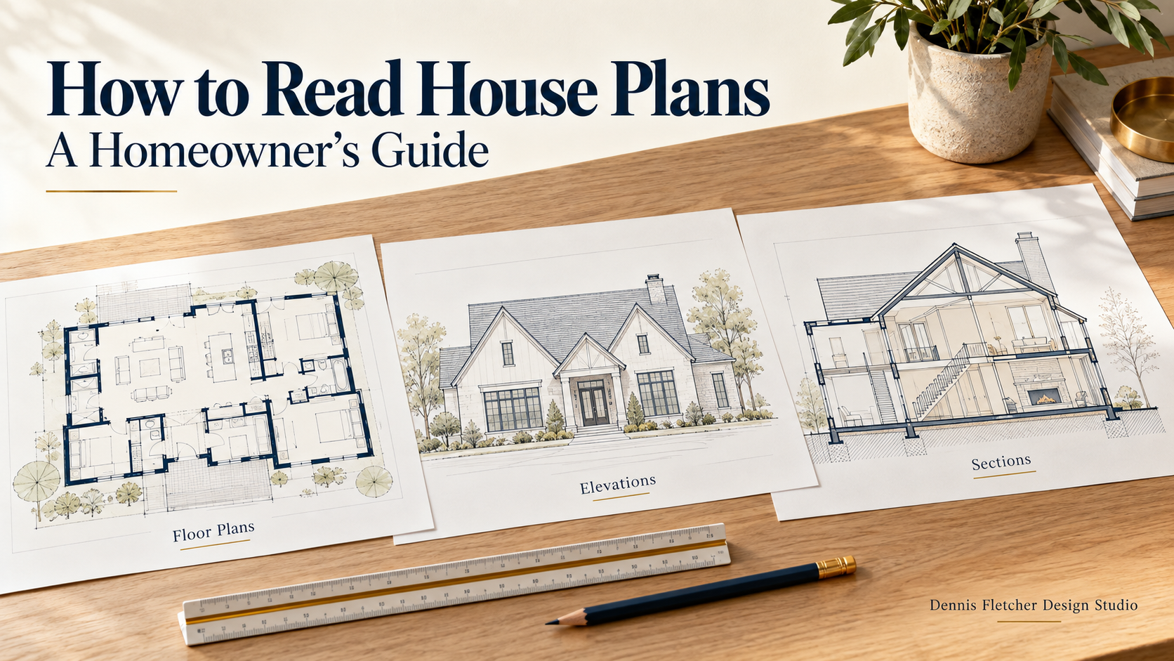
A floor plan is a horizontal cut through the building, viewed from above. It typically shows walls, doors, windows, room names, stairs, fixtures, and dimensions. Its greatest value to a homeowner is showing the relationships between spaces: where you enter, how you move, and what happens when people use neighboring rooms at the same time.
Follow a normal day through the plan. Imagine carrying groceries inside, doing laundry, welcoming visitors, and walking to a bathroom at night. Look beyond the room names. A room labeled “office” still needs enough usable wall space for your desk, storage, and a comfortable path around the furniture.
Exterior elevations: what each side looks like
An exterior elevation is a straight-on view of one side of the home. It shows the arrangement of windows and doors, roof shapes, exterior materials, and important vertical relationships. Unlike a perspective rendering, it presents that face of the building without the same sense of depth.
Compare the elevations with the floor plans. A window that works well in the front elevation must also work with the room behind it. Ask about window height, privacy, furniture placement, and how material changes meet at corners. Review all sides of the home, including the sides you may rarely see from the street.
Sections: a slice through the home
A building section shows what you would see if you sliced vertically through the home and looked at the exposed interior. Sections explain relationships that are difficult to understand from a floor plan alone, such as ceiling heights, floor levels, roof spaces, and the connection between the foundation and the occupied rooms.
For example, a staircase may fit within the floor plan while still needing careful review of the space above it. A section helps the project team explain that vertical relationship. If you have a sloping ceiling, a vaulted room, or a change in floor level, ask to see the drawing that makes its height and shape clear.
Foundation and structural drawings: what supports the home
Foundation drawings may show footings, foundation walls, slabs, piers, and other support locations. Structural information may also appear on framing plans, sections, details, or separate engineering sheets. These drawings work together to explain how the building is supported.
As a homeowner, focus on the effect on usable space and your decisions. Will a basement contain columns? Will a beam affect the ceiling? Where will equipment and access openings be located? Leave the sizing and verification of structural components to the responsible professionals. An open area on the floor plan does not, by itself, explain how the space above it is supported.
Construction details: how parts come together
Details are enlarged drawings of specific conditions. They can explain how a porch joins the house, how materials meet around an opening, or how a roof and wall connection is assembled. They allow important information to be shown clearly without crowding the main plans.
You do not need to understand every line in a detail. You should understand why the detail exists and whether it affects an appearance, material, or feature you care about. If you want to change a material, ask whether that change also affects related details.
Electrical and other system drawings: how the home functions
Electrical plans commonly show lighting, switches, receptacles, and other devices using symbols identified in a legend. Mechanical and plumbing information may be included in the set or developed separately, depending on the project scope.
Review these drawings with furniture and daily routines in mind. Where will you read, charge devices, use small appliances, or turn on a light when entering a room? A lighting symbol indicates a planned fixture location, but it may not settle the fixture selection, brightness, or every control preference. Ask what is specified and what still needs a decision.
Learn the few drawing conventions that unlock the set
Dimensions and scale
Dimensions are the written measurements shown on drawings. A chain of dimensions may identify several smaller distances, while another dimension shows the overall length. Read the endpoints carefully: a measurement might run between framing faces, finished surfaces, centerlines, or other defined points.
Never assume a room label tells you the exact clear space available for furniture. Ask how that dimension is measured and account for cabinetry, trim, door movement, and circulation. If a measurement looks inconsistent, request clarification rather than trying to resolve it by measuring the page.
Scale describes the relationship between the drawing and the actual building. For example, at a stated scale of 1/4 inch equals 1 foot, a one-inch line represents four feet—provided the drawing is printed at the intended size. Screens, reduced prints, and “fit to page” settings can change the apparent scale. Use written dimensions for decisions and ask about missing measurements.
Line types and door swings
Heavy or dark lines often identify elements cut through in that view, while lighter lines may show objects beyond. Dashed lines can indicate overhead, hidden, existing, or other features, depending on the drawing conventions. Check the legend and notes before assigning a meaning.
A curved arc at a hinged door commonly shows its swing. Follow that arc to see how the door interacts with a vanity, another door, or a walking path. Sliding and folding doors use different symbols. An opening that looks generous with every door closed may function differently during normal use.
Callouts, tags, and schedules
A callout directs you to related information elsewhere in the set. A section marker typically identifies both the view and the sheet where you can find it; its arrow indicates the direction of view. In a common numbering system, a reference such as 2/A5.1 means view or detail 2 on sheet A5.1. Your set’s legend explains its specific system.
Window and door tags often refer to schedules. Here, “schedule” means an organized table of information, not a construction timeline. A window schedule may identify sizes, types, and notes associated with each tag. Always read the table and its notes together; a short label does not necessarily describe every product requirement.
Follow one feature through several sheets
A kitchen window is a useful example. The floor plan shows where it sits in the wall and how it relates to the sink and cabinets. The exterior elevation shows its appearance from outside. A schedule may define its size and type. A section or detail may explain its height or the surrounding assembly.
If you want a taller window, the change may affect more than the elevation. The designer may need to coordinate it with cabinetry, the countertop, structural information, and exterior details. This is why changing a single drawing without reviewing the connected information can create confusion.
The same method works for a fireplace, stair, covered porch, or large opening. Ask: Where is it? What does it look like? How high is it? What information explains how it is built? Those four questions help you navigate the set without needing to know every technical term.
Review the plans in three manageable passes
First pass: understand the home
Read the cover sheet and index, then look through the floor plans and elevations. Focus on the overall layout, orientation, room relationships, and exterior character. Ask your designer to explain unfamiliar symbols as they appear. Trying to solve every detail during this pass can make it harder to judge the larger design.
Second pass: test everyday life
Add realistic furniture sizes and walk through daily activities. Think about carrying laundry, opening appliances, storing coats, using outdoor spaces, and moving through the home with visitors. Compare room arrangements with window locations, door swings, and ceiling conditions. Identify the few measurements that are particularly important to your household.
Third pass: confirm decisions and coordination
Review the sections, details, schedules, and system drawings with the project team. Separate confirmed choices from items still awaiting selection or additional information. Ask where each important decision is documented and who will provide any remaining drawings or specifications.
Keep a written question list with the sheet number, room or feature, and the decision needed. For example: “Kitchen floor plan: Will the pantry door interfere with the refrigerator when both are open?” is easier to answer and track than “The kitchen seems tight.”
A homeowner’s plan-review checklist
- I know the date, revision, and intended use of the drawing set I am reviewing.
- I can find the major drawings using the sheet index.
- I understand how the house sits on the property and where I will enter.
- I have tested the room layout with realistic furniture and everyday activities.
- I have checked important door swings, storage areas, and walking paths.
- I have compared windows and doors across plans, elevations, and schedules.
- I understand important ceiling heights, stairs, and changes in floor level.
- I have reviewed lighting and device locations around how I will use each space.
- I know which materials, fixtures, and other selections remain undecided.
- My questions and requested changes are recorded for the project team.
Common mistakes to avoid
Reviewing only the floor plan. Room arrangement matters, but it does not explain every height, exterior condition, or construction relationship. Review the connected views before approving a feature.
Assuming anything missing is included. A drawing may not specify every finish, appliance, accessory, or installation responsibility. Ask where those items are documented and whether they are included in the project scope and builder’s pricing.
Mixing old and new sheets. Keep the current coordinated set together and clearly separate superseded drawings. Before a pricing or construction decision, confirm with the project team which issue applies.
Treating a verbal change as a finished revision. A conversation is the beginning of a change. Ask how it will be documented, reviewed, and communicated to the people affected. A seemingly small adjustment can require updates on several sheets.
Waiting until construction to ask. If you cannot picture something, ask for an explanation, marked-up view, or appropriate three-dimensional illustration during design. Resolving uncertainty before work begins helps protect the choices that matter most to you.
Your role is to understand, question, and communicate
Builders, designers, engineers, inspectors, and homeowners use the same drawing set for different purposes. Your role is to explain how you want to live, understand the proposed result, and call attention to anything that does not make sense to you. The responsible professionals handle technical design and verification within their scopes.
A good plan review is a conversation. You should be able to ask why a column is present, what a ceiling will feel like, or how a doorway affects furniture without feeling that you need to know the technical answer first.
At Dennis Fletcher Design Studio, I approach residential design as a process of building clarity. Understanding the plans gives you a stronger voice in that process and helps the whole team work toward the same home. Taking time to ask clear questions is part of making sound decisions.
Thinking about building, adding on, or redesigning your home?
If you’re early in the planning process—or even just trying to figure out where to start—I offer a free 30-minute phone consultation to talk through your ideas, answer questions, and help you understand next steps.
📧 Email: info@dennisfletcherdesignstudio.com
📅 Schedule your free consultation here:
👉 Schedule a free 30-minute phone consultation
Follow me on the following Social Media Pages:
Facebook | Instagram | TikTok | YouTube
Leave a Reply